-
Training project · Truck
TRUCK.BATCH PRODUCTION WITH A TOLERANCE SYSTEM.
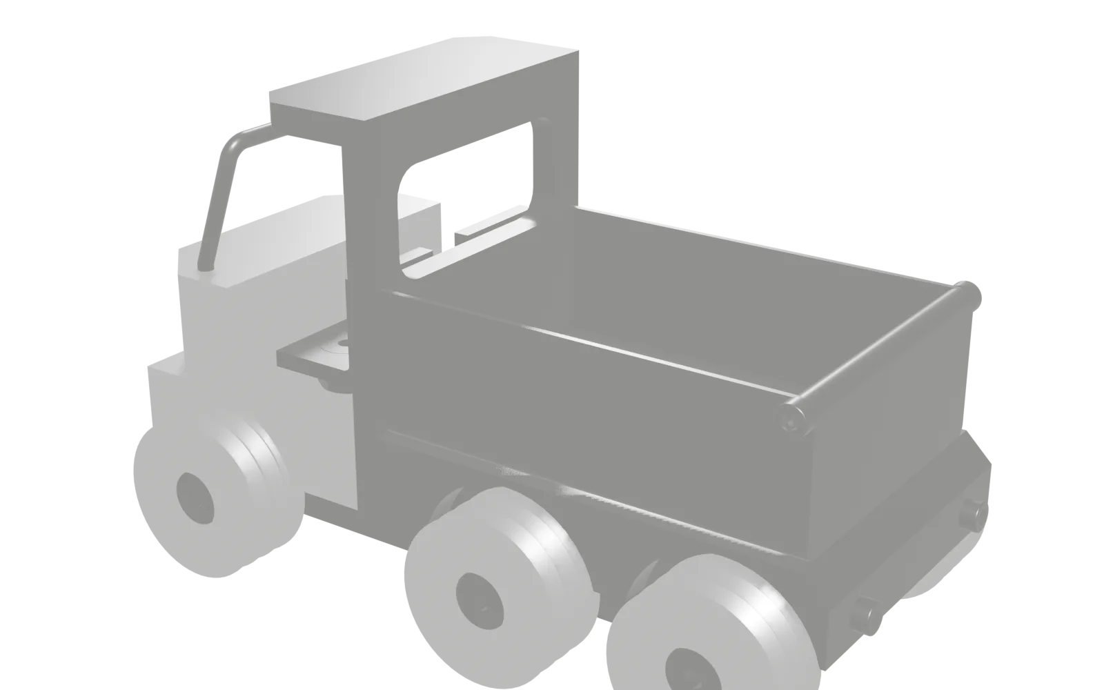
H13 counterbores, ±0.1 grids and 0.01 runout: the batch-scale successor to the buggy. What you see is our own design model from Fusion: 43 bodies, about 15 centimetres long. Scroll: the model opens up part by part.
-
01 / 11
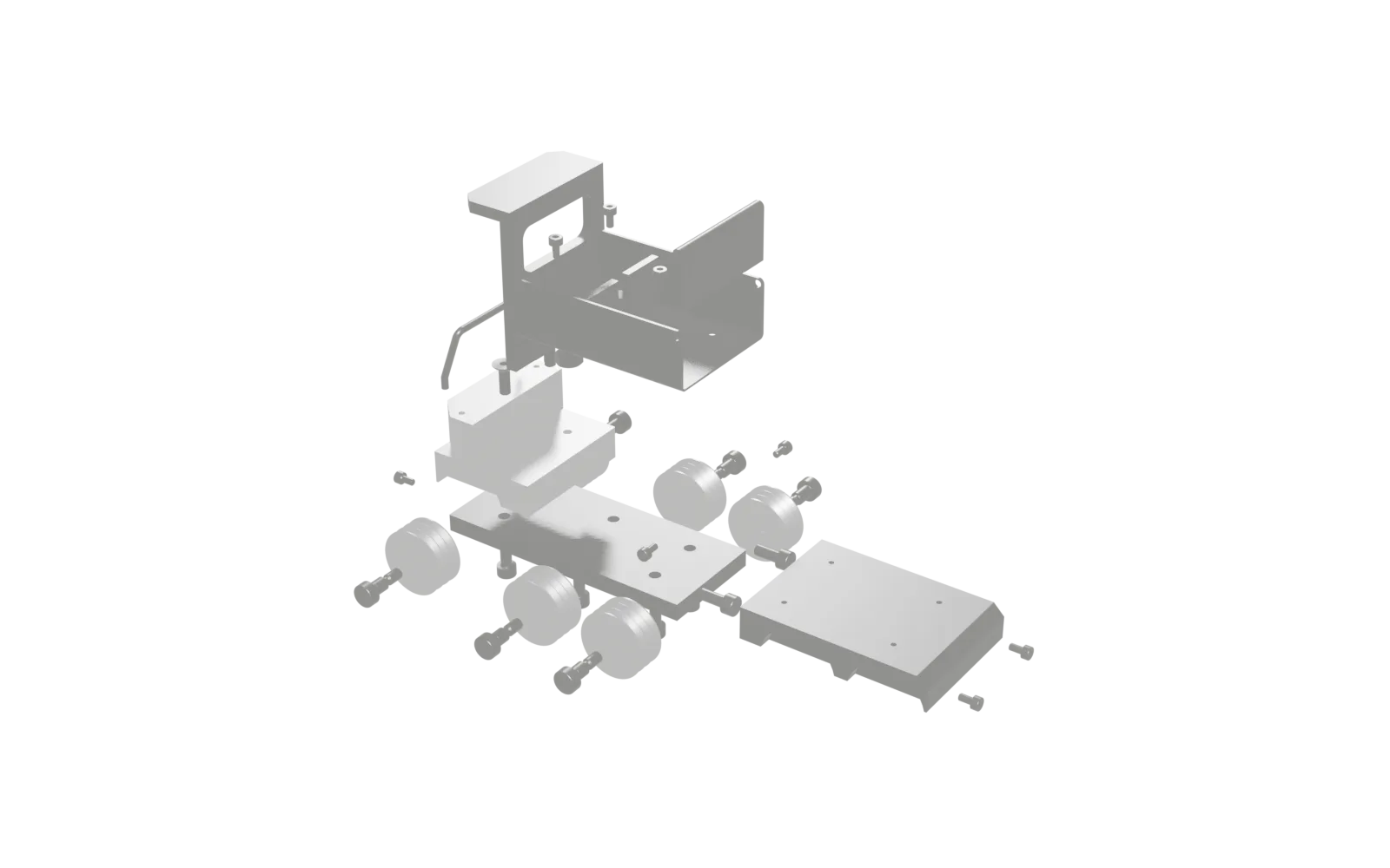
9 PARTS.EACH ONE MADE.
Milling, turning and sheet-metal project with a consistent tolerance system: six counterbores Ø5.5H13/Ø10H13 on a 40±0.1 grid, wheels with a Ø6H7 bore and 0.01 runout to datum A, the only explicit geometrical tolerance in the portfolio. 15 BOM items, six wheels, 145×77×90 mm, about 1.6 kg.
-
02 / 11
TRUCK CHASSIS.MILLED.
The truck chassis is the base plate of the whole vehicle: a steel plate 120 × 50 × 8 mm weighing about 340 g on which engine block, trailer plate, roof and the wheel mountings sit.
What this part involves
- Check the blank and face-mill the datum face
- Mill the opposite face to 8 mm
- Mill the length 120±0.1 and the width 50±0.1
- Define the datum edge and probe the hole pattern
-
03 / 11
TRUCK ENGINE BLOCK.MILLED.
The truck engine block is the cab of the vehicle and, at about 170 g from a raw volume of 105 cm³, the part with the highest machining share in the whole project: 39.5 % of the raw material is milled away.
What this part involves
- Mill the blank to 60 × 50 × 35 mm
- Set the datum edge and probe the hole pattern
- Spot and drill all holes
- Bring the Ø3 +0.1/0 holes to size
-
04 / 11
TRUCK TRAILER PLATE.MILLED.
At about 520 g the trailer plate is the heaviest part of the truck and carries a third of the total mass.
What this part involves
- Check the blank and face-mill the datum
- Mill the opposite face to 15 mm and the width to 60±0.3 mm
- Define the datum edge and probe the grid pattern
- Spot and drill the core holes
-
05 / 11
TRUCK ROOF.MILLED.
The LKW roof closes the cab at the top and, at about 170 g, is an angle part of steel: a base plate 70 × 60 mm, 5 mm thick, with a leg of 25 mm overall height and 5 mm thickness at the 70 mm end, i.e.
What this part involves
- Mill the blank to 70 × 60 × 25 mm
- Finish the seating face to Ra 3.2
- Mill the L-shape with 5 mm wall thickness
- Drill the start hole for the window cut-out
-
06 / 11
LOADING FLOOR.BENT.
The loading floor is the truck's first genuine sheet-metal part: a U-bent steel sheet only 1 mm thick weighing about 65 g, with 80 × 26 mm side walls and an R2.5 mm internal radius at both bends.
What this part involves
- Calculate the flat blank and define the blank size
- Check the sheet and cut the blank
- Mark out the hole pattern and the bend lines
- Drill the four Ø3.4 mm holes in the flat state
-
07 / 11
LOADING EDGE.MILLED.
At about 51 g the loading edge is the truck's most unassuming and, in calculation terms, most accurate part: a steel strip 54 −0.2/0 × 25 × 5 mm with a half-round R2.5 top edge and two M3 threads in its end faces.
What this part involves
- Check the blank and confirm the stock dimensions
- Face-mill the first end face
- Mill the length to 53.90 mm
- Clamp the end face on edge and spot the thread position
-
08 / 11
TRUCK TYRE.TURNED.
The truck tyre is the most important part in the entire set: it is the only part in all four projects whose drawing carries an explicit geometrical tolerance, a circular runout tolerance of 0.01 mm referred to datum A, the Ø6H7 bore.
What this part involves
- Clamp the round bar and face the end
- Centre and pre-drill Ø5.8 mm
- Produce the Ø11H13 hub recess to 5.4 mm depth
- Ream the Ø6H7 fitted bore
-
09 / 11
TRUCK SEAT.MILLED.
The truck seat is a 20 × 20 × 20 mm angle in steel weighing about 16 g, needed twice, driver's and passenger's seat of the cab.
What this part involves
- Check the blank and plan the clamping
- Mill the blank to size
- Clear the corner
- Run the last cut and check the wall thickness
-
10 / 11
TRUCK WINDSCREEN.MILLED.
With about 6 g the windscreen is the lightest part of the LKW and its only wire-bent part, neither sheet-metal nor milled part: a U-bracket of round wire Ø3 mm, 50±0.1 mm wide and 25 mm high, whose two feet are angled at 165° over 5 mm of length.
What this part involves
- Measure the wire diameter and calculate the wire length
- Clarify the reference of the bracket dimension
- Cut the wire and deburr the cut faces
- Trial bend on an offcut
-
11 / 11
ASSEMBLED.INSPECTED.
Produce and inspect parts to drawing. Apply tolerances, fits and surface specifications.
What this part involves
- Check completeness against the parts list
- Calculate the mass balance and compare it with the title block
- Measure the wheel diameters and match the wheels
- Bolt the engine block and trailer plate onto the chassis
Model: Autodesk Fusion, Stern Didactic. Taken over without simplification; what is hidden in Fusion is missing here too.