-
Training project · Buggy
BUGGY.SHEET METAL AND MACHINING PROJECT.
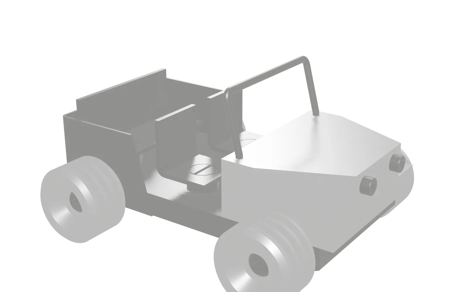
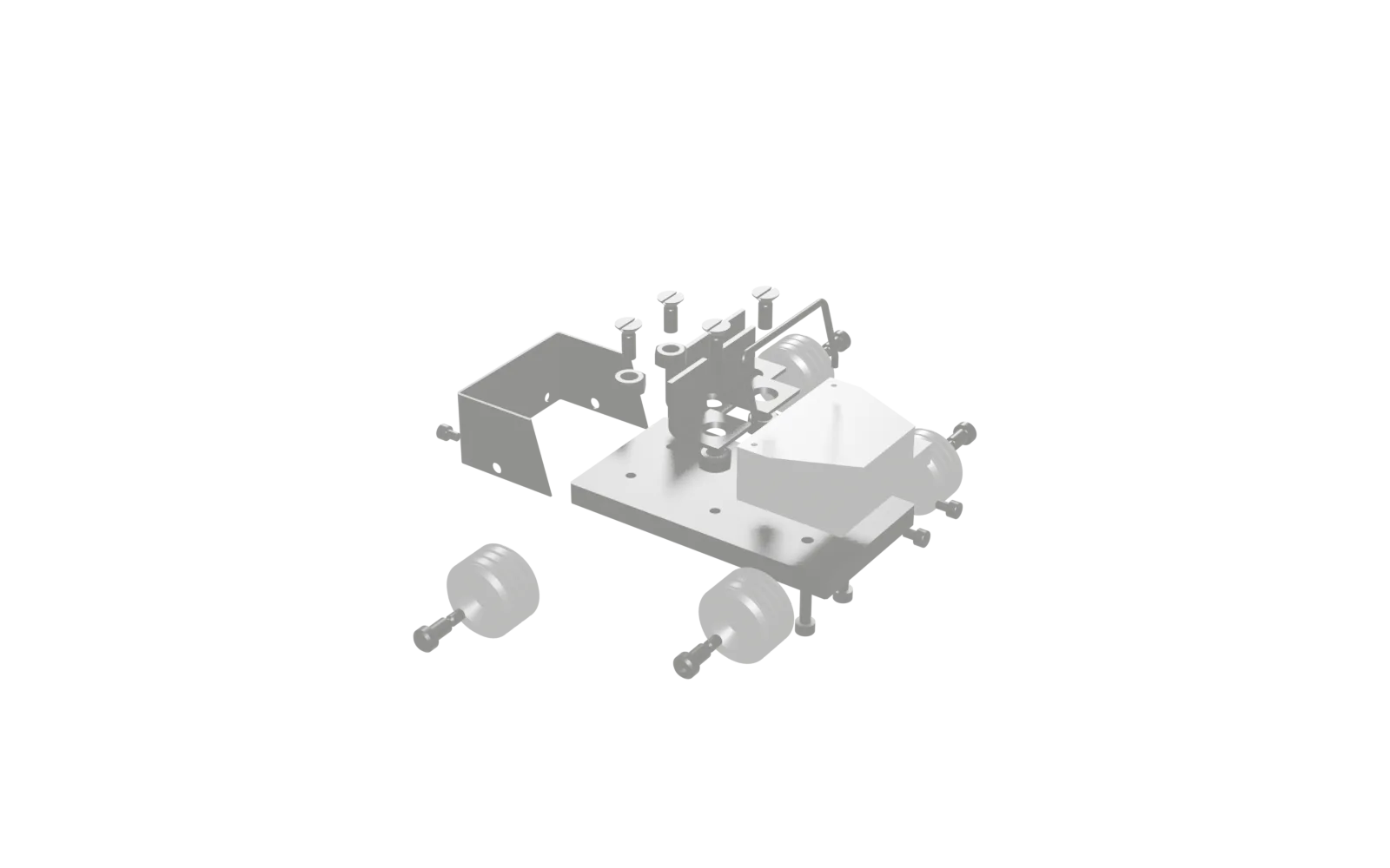
Bending, unfolding, milling and turning: from sheet blank to a rolling buggy. What you see is our own design model from Fusion: 29 bodies, about 15 centimetres long. Scroll: the model opens up part by part.
-
01 / 09
7 PARTS.EACH ONE MADE.
Training project focused on sheet metal: U-bent rear body with a dimensioned flat pattern (170.52 mm), sheet angles, a wire bending part, combined with a milled steel chassis, aluminium engine block and turned wheels on ISO 7379 shoulder screws.
-
02 / 09
CHASSIS.MILLED.
At about 690 g the chassis is the heaviest part of the buggy, more than half of the total mass of about 1.3 kg sits in this steel plate alone.
What this part involves
- Check the blank and mill the datum face
- Mill the opposite face parallel to 10 mm
- Mill the four sides to 130 × 70 mm
- Mark out or program the top-view hole pattern
-
03 / 09
ENGINE BLOCK.MILLED.
The engine block is the most demanding milled part of the buggy: an aluminium block 70 × 50 × 25 mm with a prismatic trapezoidal pocket, angled faces, M4 threads and Ø3 +0.1/0 holes.
What this part involves
- Clamp the blank and mill the datum face
- Mill the opposite face to 25 mm and the four sides to 70 × 50 mm
- Set the zero and create the setup in Autodesk Fusion
- Program facing, two operations
-
04 / 09
WHEEL.TURNED.
The wheel is the buggy's only turned part and the only part in the whole project with a genuine ISO fit.
What this part involves
- Clamp the bar and face it
- Centre and pre-drill Ø5.8 mm
- Rough and finish the Ø34 outside diameter
- Turn the Ø21 collar and Ø11 hub with the 11 and 5 steps
-
05 / 09
REAR BODY.BENT.
The rear body is the didactic heart of the buggy project: a U-shaped folded steel sheet 1 mm thick whose flat pattern is explicitly dimensioned on the drawing as 170.52 × 35 mm.
What this part involves
- Measure the sheet thickness and calculate the flat pattern
- Trial bend on an offcut
- Mark out the flat pattern
- Cut the strip to length and width
-
06 / 09
SEAT.BENT.
The seat is a simple sheet metal angle 25 × 25 × 25 mm from 2 mm steel sheet with one 90° bend, and of all things the project's smallest sheet part contains the elegant calculation.
What this part involves
- Measure the sheet thickness and calculate the flat pattern
- Trial bend on an offcut
- Mark out the strip, both seats together
- Drill the Ø8.6 mm holes
-
07 / 09
BENCH SEAT.BENT.
The bench is the same sheet metal angle as the seat, cross-section 25 × 25 mm from 2 mm steel sheet, one 90° bend, an identical developed length of 46.52 mm.
What this part involves
- Measure the sheet thickness and calculate the flat pattern for the family
- Trial bend for the whole family
- Cut the strip and cut the widths
- Mark out the hole centres from the part centre
-
08 / 09
WINDSCREEN.BENT.
At about 6.5 g the windscreen is the buggy's lightest part and the project's only wire bent part: a U-shaped bracket from Ø3 mm round wire, 60 mm wide and 25 mm high, whose two feet are bent over 5 mm of length at 165° and serve as insertion tabs.
What this part involves
- Measure the wire diameter and calculate the flat pattern
- Mass calculation as a cross-check
- Cut the wire with allowance and deburr the ends
- Trial bend on an offcut
-
09 / 09
ASSEMBLED.INSPECTED.
Produce and inspect parts to drawing. Apply tolerances, fits and surface specifications.
What this part involves
- Incoming inspection of all 29 parts
- Recalculate the mass balance
- Pre-measurement on the chassis and the wheels
- Lay the chassis down as the base and fit the mounted parts hand tight
Model: Autodesk Fusion, Stern Didactic. Taken over without simplification; what is hidden in Fusion is missing here too.