-
Training project · Wind turbine
WIND TURBINE.MACHINING PROJECT.
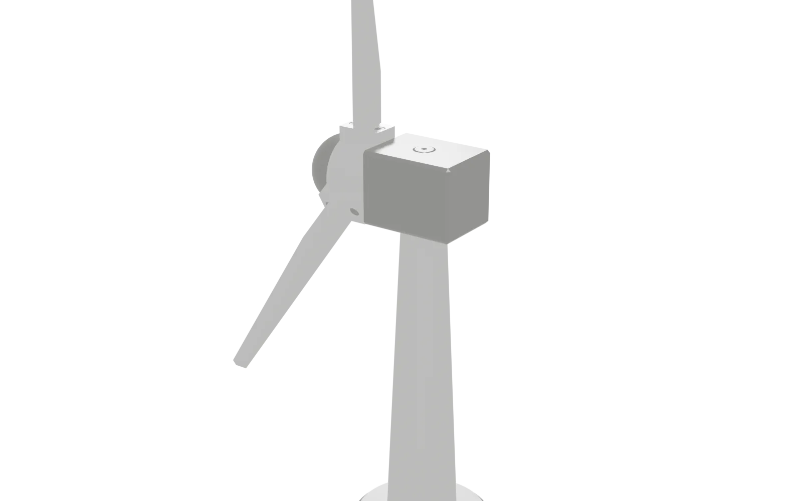
Turning, milling, fits and assembly: from steel and aluminium stock to a working wind turbine. What you see is our own design model from Fusion: 25 bodies, about 41 centimetres tall. Scroll: the model opens up part by part.
-
01 / 09
7 PARTS.EACH ONE MADE.
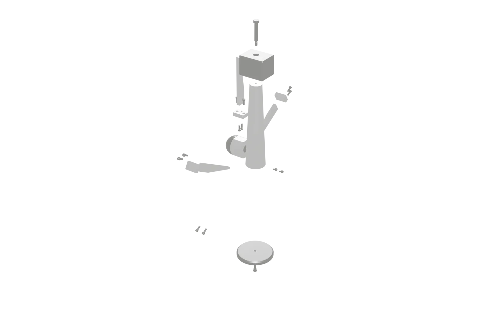
Classic metal-trades training project: seven parts in steel and aluminium are turned, milled, drilled, reamed and threaded, with real ISO fits (Ø20H8/e8 sliding fit, Ø8H7 for the ISO 7379 shoulder screw), roughness down to Ra 0.8 and a DIN 76-A thread undercut.
-
02 / 09
BASE PLATE.TURNED.
The Ø98 × 10 mm steel disc is the foot of the wind turbine and the source of its stability: at about 580 g it carries about 18 % of the total mass of about 3.2 kg and keeps the 413 mm column upright.
What this part involves
- Prepare the blank and establish setup 1
- Face the first end
- Centre drill and drill the Ø6.6 mm through hole
- Produce the Ø11 × 6.4 mm counterbore
-
03 / 09
TURBINE TOWER.TURNED.
The tower is the longest part of the project and its machining centrepiece: an aluminium truncated cone, 220 mm long, Ø50 mm at the bottom and Ø30 mm at the top.
What this part involves
- Calculate the taper data and define the method
- Clamp the blank and face the first end
- Drill the Ø5 mm tapping hole to a depth of 20 mm
- Cut the M6 thread to a depth of 15 mm
-
04 / 09
NACELLE.MILLED.
At about 1.2 kg the nacelle is the heaviest part of the project, 37.93 % of the total mass, and its most demanding milled part: a steel block 65 × 50 × 50 mm in which three completely different types of hole come together.
What this part involves
- Align the vice and clamp the blank
- Mill the datum face and the opposite face
- Mill the four side faces square
- Mark out or program the hole positions
-
05 / 09
HUB.TURNED.
The hub is the rotor hub of the wind turbine and carries the didactically most important fit of the project: its central Ø20H8 bore with Ra 0.8 runs on the Ø20e8 shank of the shaft and thereby forms a pure clearance fit.
What this part involves
- Calculate the fit before the first chip
- Clamp the blank, face and pre-drill
- Bore to Ø19.8 mm and finish the outside diameter
- Re-clamp and produce the width
-
06 / 09
SHAFT.TURNED.
The shaft is the turned part with the highest density of requirements in the project: a steel part with a Ø50 mm hemispherical head, a Ø20e8 fit shank with Ra 0.8.
What this part involves
- Calculate the length chain and fit in advance
- Clamp the blank, face and rough the outside contour
- Turn the threaded spigot and cut the DIN 76-A undercut
- Turn the M12 thread
-
07 / 09
WING SEAT.MILLED.
At about 13 g the wing seat is the smallest and lightest part of the turbine and is needed three times: it connects one wing each to the hub.
What this part involves
- Clamp the blank strip and mill the datum face
- Mill the 20 mm width and check squareness
- Mark out or program the hole positions from the reference edge
- Centre and drill the four Ø4.5 mm holes
-
08 / 09
TURBINE BLADE.MILLED.
The turbine blade is a 125 mm milled aluminium part (about 38 g) tapering from 20 mm at the root to 5 mm at the tip.
What this part involves
- Cutting and face milling
- Marking and centre-punching
- Tap drilling
- Tapping M4
-
09 / 09
ASSEMBLED.INSPECTED.
Produce turned and milled parts to drawing, applying general and ISO tolerances confidently. Produce and measure fits (H8/e8, H7) and judge their function.
What this part involves
- Pre-assembling the rotor
- Screwing the axle into the head
- Fitting the rotor
- Tower onto the base
Model: Autodesk Fusion, Stern Didactic. Taken over without simplification; what is hidden in Fusion is missing here too.